Overview
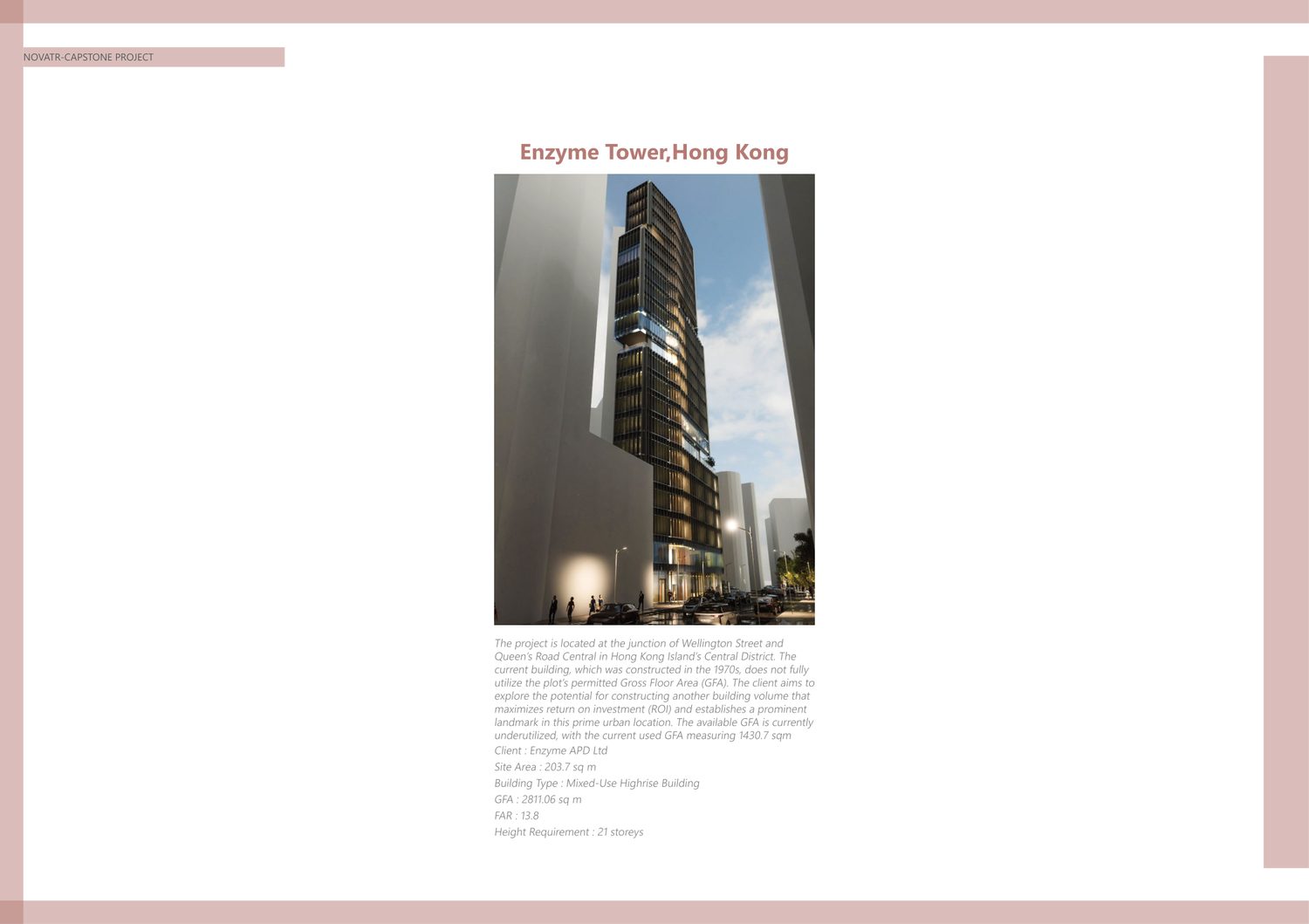
The capstone for the Novatr BIM Professional Program, graded A+. A 1970s building at the junction of Wellington Street and Queen's Road Central in Hong Kong's Central District was under-using its permitted floor area — 1,430.7 m² of 1,900+ available. The brief was to recover that value as a new landmark volume.
| Client | Enzyme APD Ltd |
| Site area | 203.7 m² |
| Type | Mixed-use high-rise |
| GFA | 2,811.06 m² |
| FAR | 13.8 |
| Height | 21 storeys |
Why this project is here
The professional work on this site shows production and tooling. This one shows the management layer — the part of BIM that sits above modelling: working to a client's BEP, identifying BIM users, understanding the MIDP matrix, and running a project through the full RIBA Plan of Work rather than joining it mid-stage.
It is academic, and labelled as such. But it is the only project here that covers Stages 0 through 7 end to end, including 4D sequencing and 5D cost planning.
RIBA Plan of Work — Stages 0 to 7
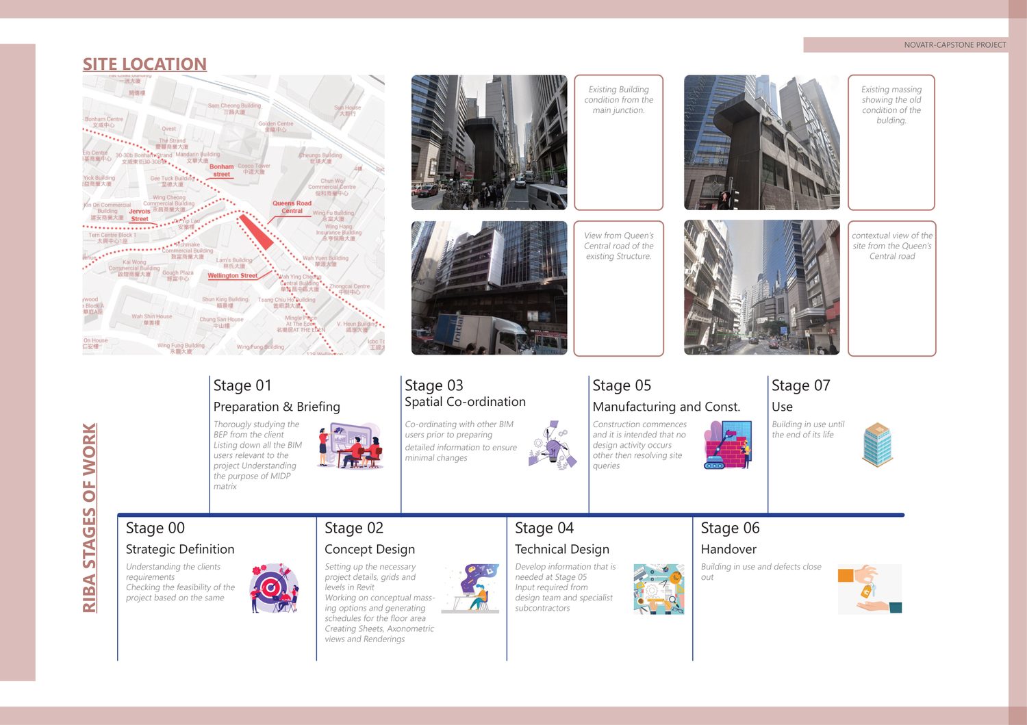
Each stage carried its own deliverable: client requirements and feasibility at Stage 0–1, conceptual massing and area schedules at Stage 2, coordination with other BIM users at Stage 3, technical information at Stage 4, construction with no design activity beyond site queries at Stage 5, handover and defects close-out at Stage 6, and building-in-use at Stage 7.
Stage 1 specifically meant studying the client's BEP, listing every BIM user relevant to the project, and understanding the purpose of the MIDP matrix before any information was produced.
Recovering the floor area
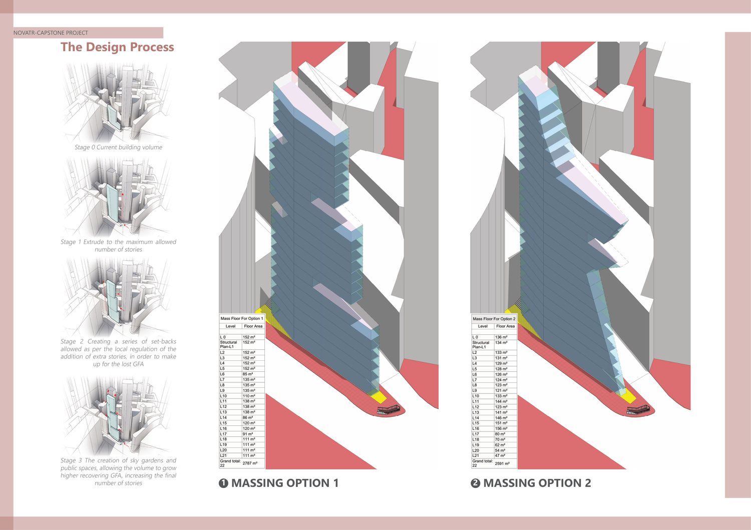
The massing is an argument, worked in four moves: extrude to the maximum permitted storeys, introduce the set-backs local regulation requires, then recover the lost GFA by adding sky gardens and public space that allow the volume to grow higher again. Two options were carried forward with full per-level area schedules.
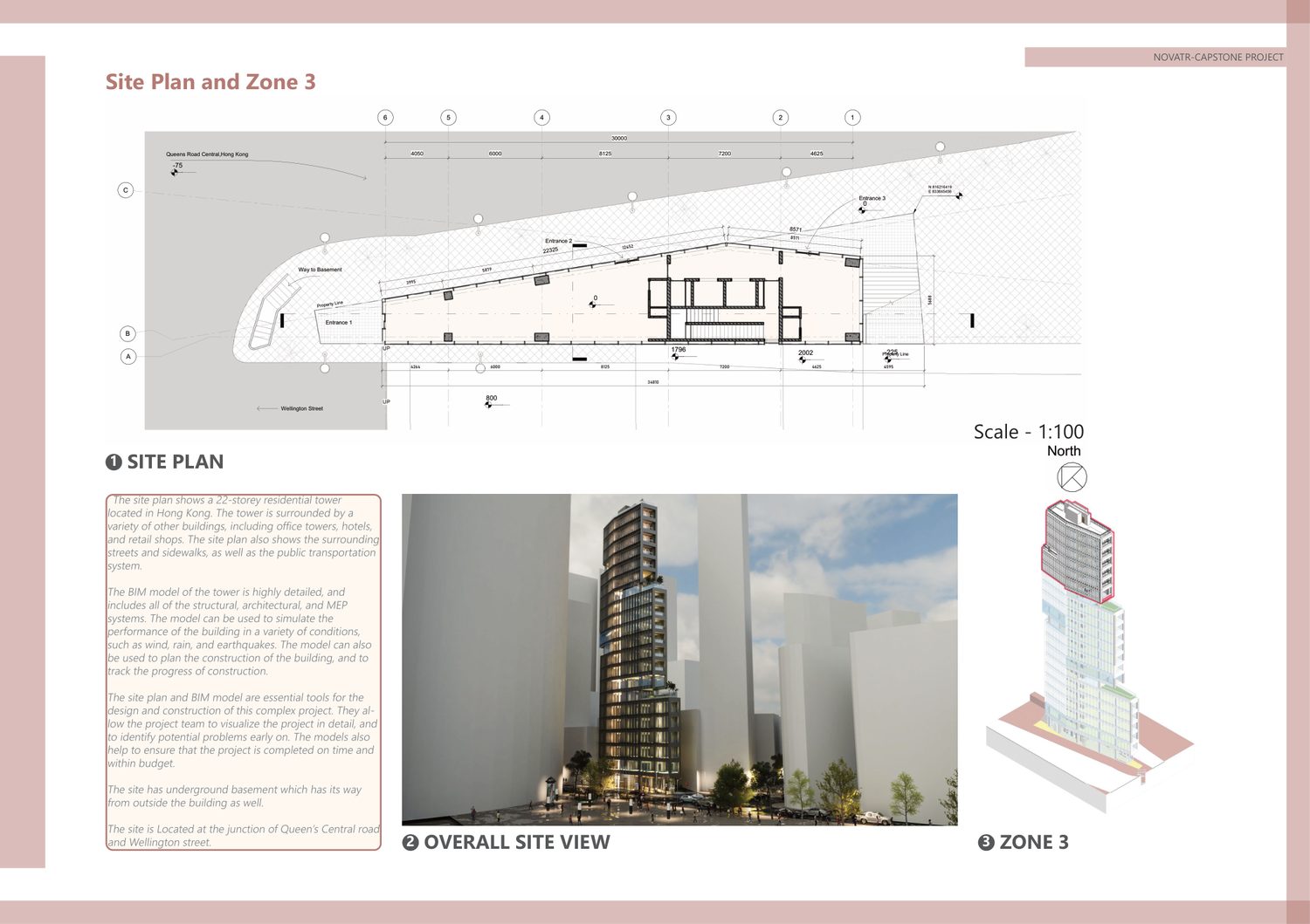
Documentation set
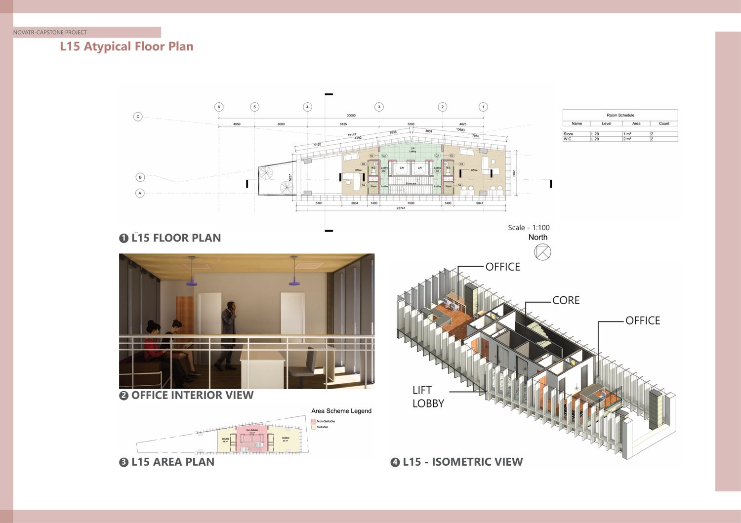
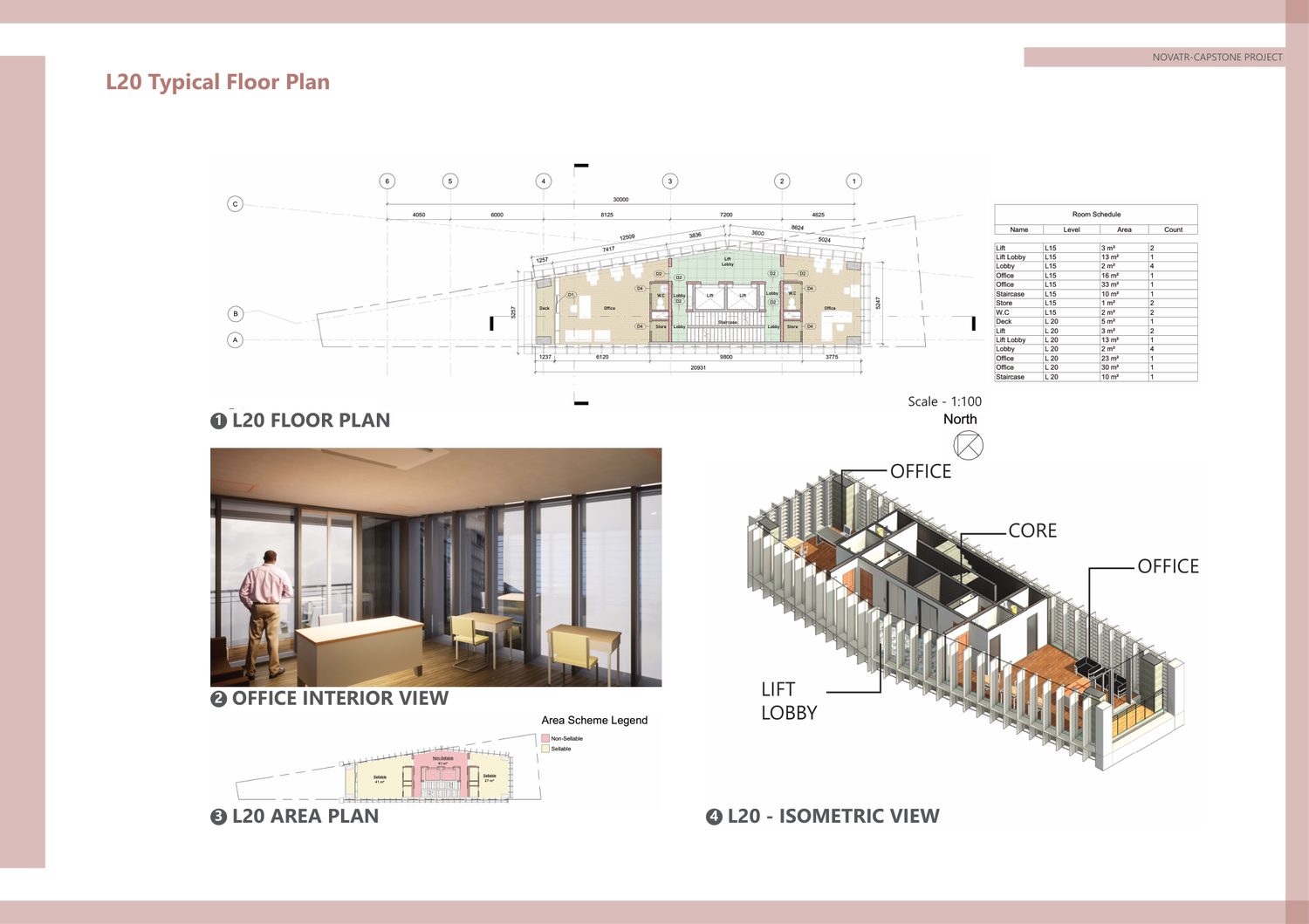
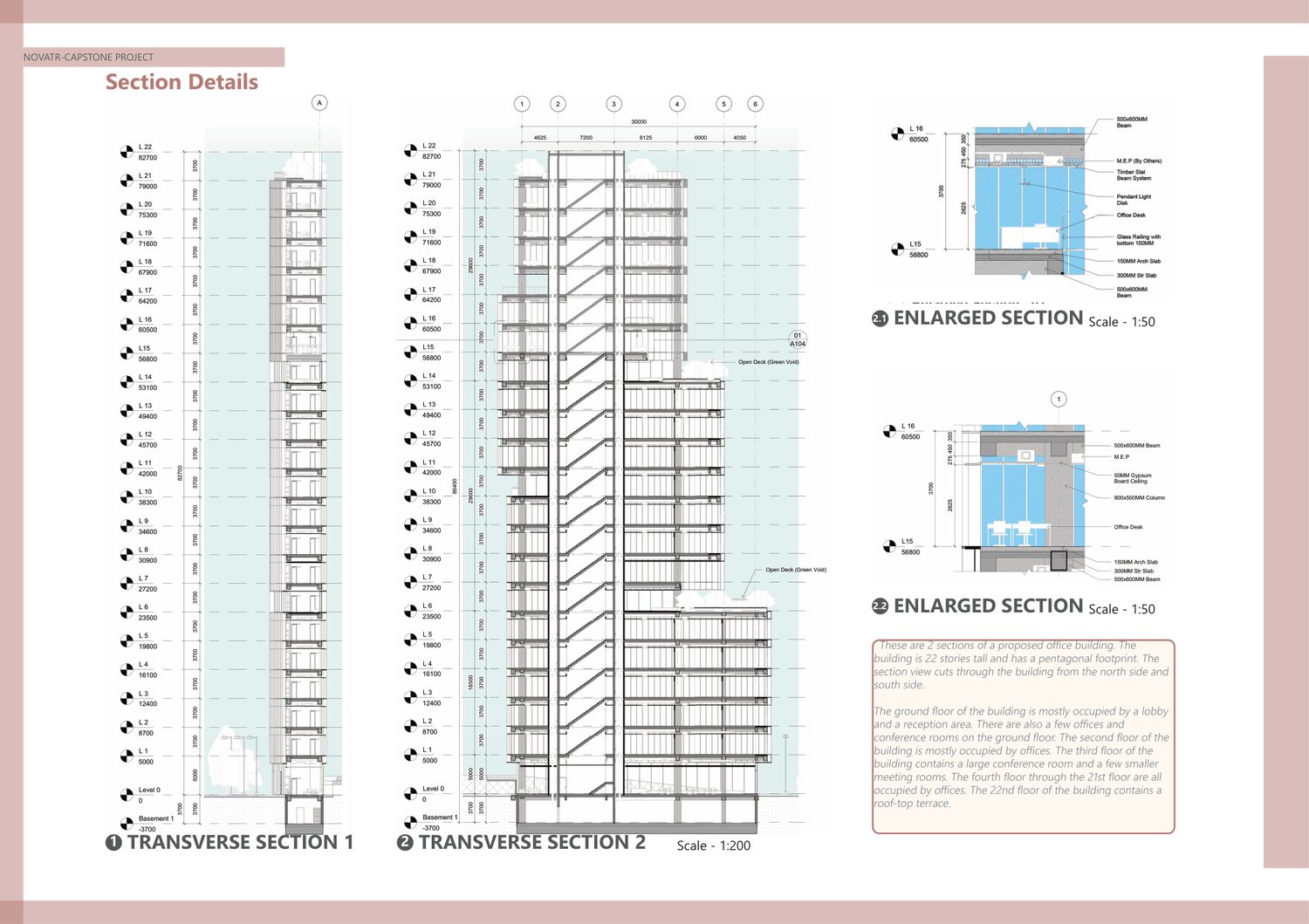
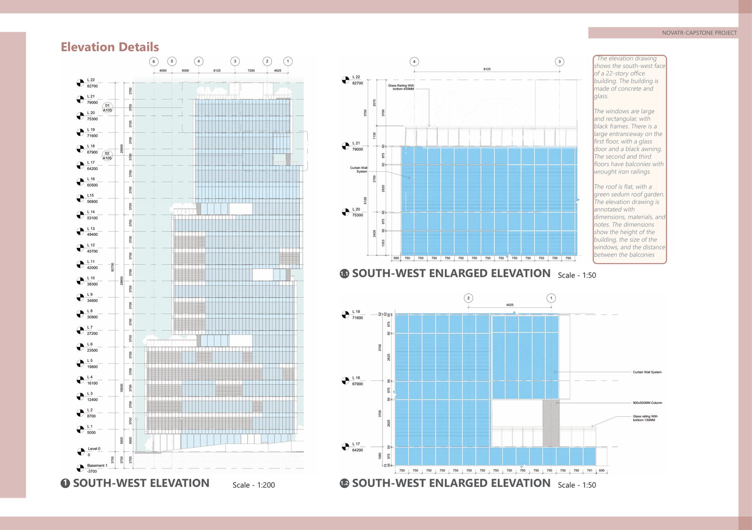
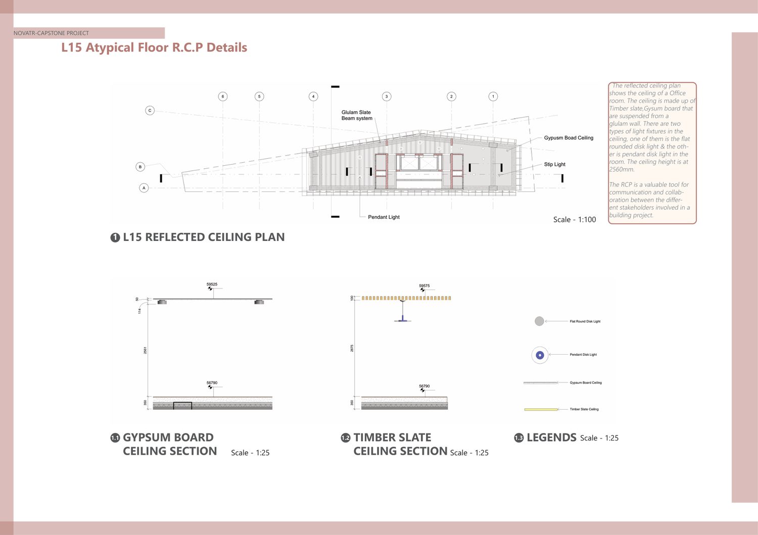
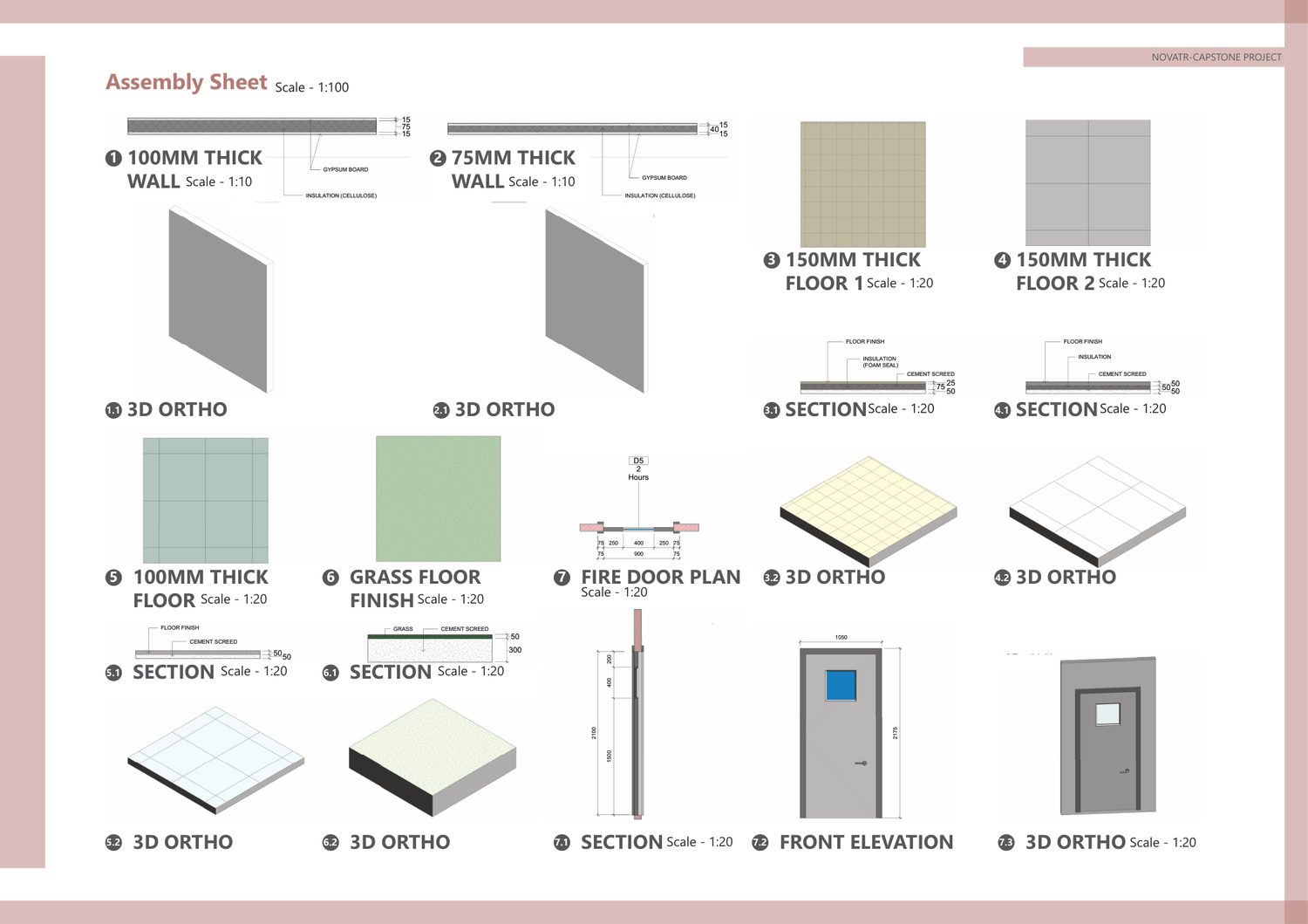
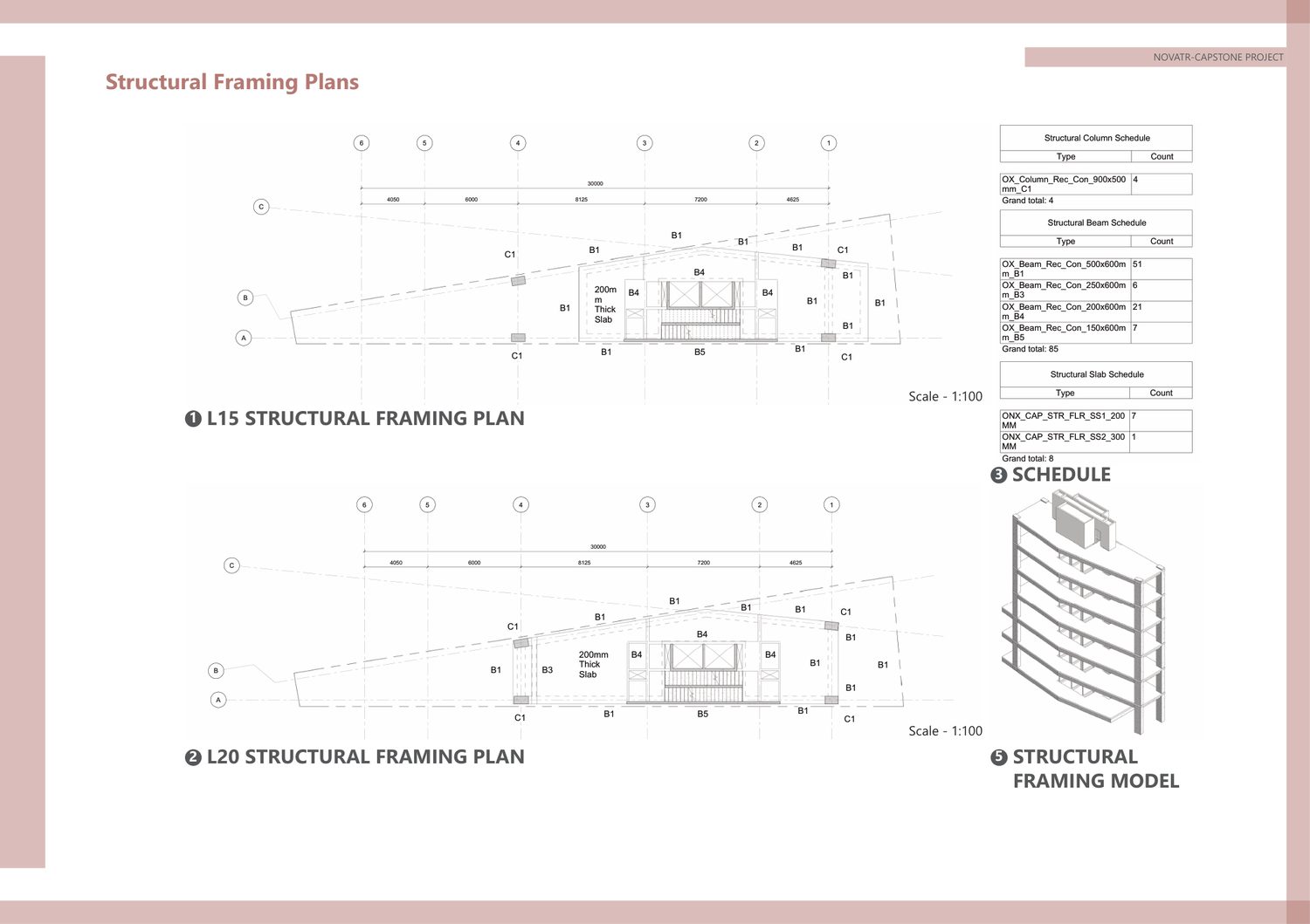
The assembly sheet is the one worth pausing on: every build-up drawn at 1:10 to 1:20 with a matching 3D orthographic, so a build-up can be read as a section and as an object.
Parametric families
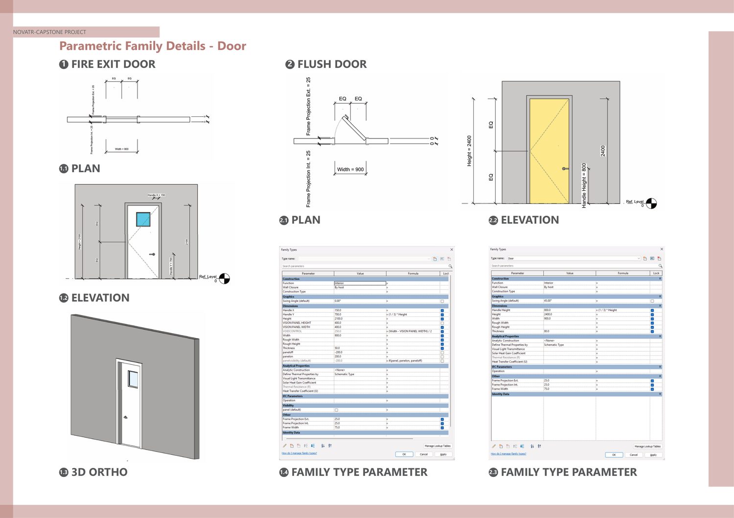
Fire exit and flush door families authored with exposed type parameters — the same discipline as the balcony railing family, three years earlier.
Coordination and clash resolution
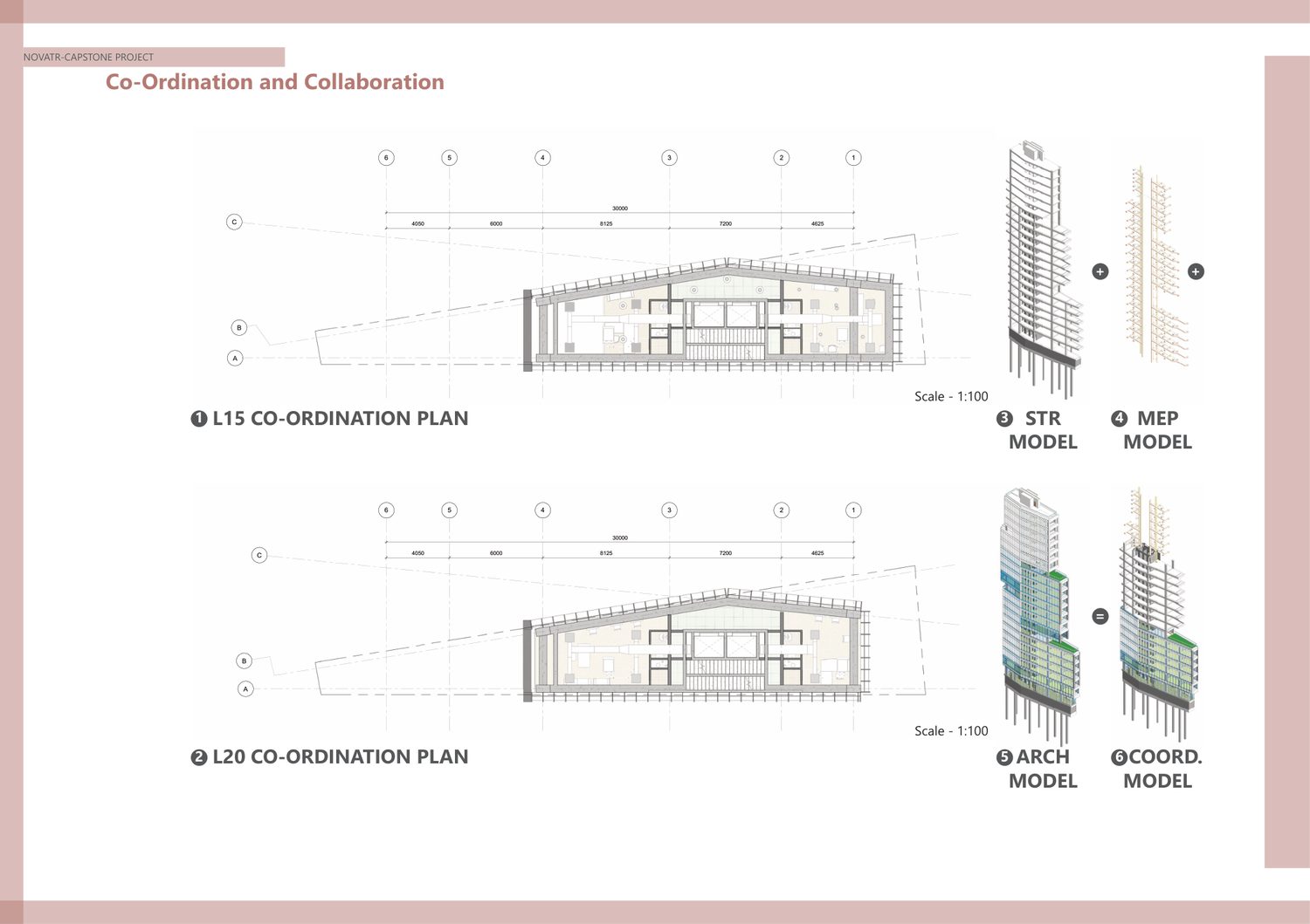
Architectural, structural and MEP carried as separate models and federated into a coordination model per level.
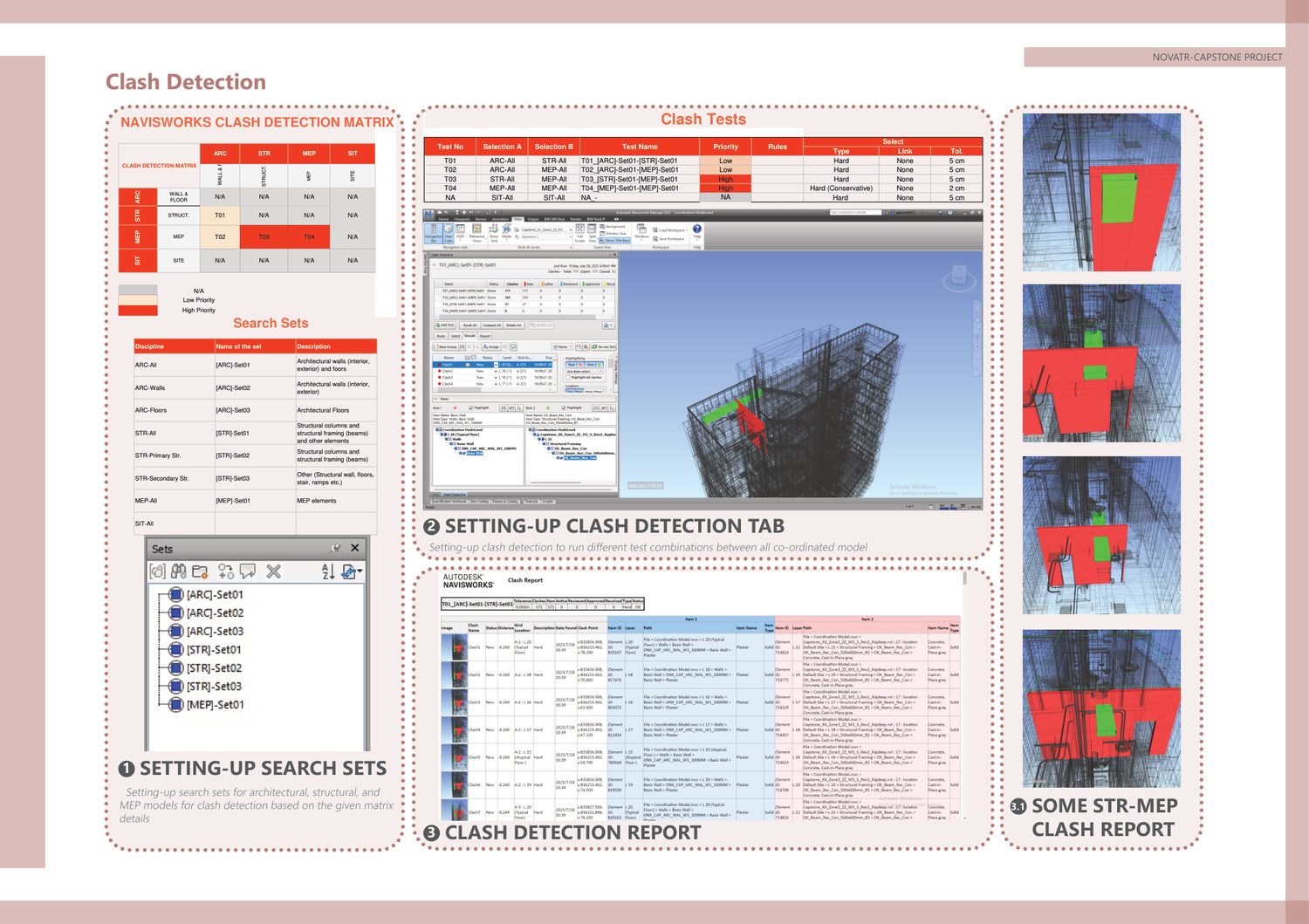
A clash detection matrix defines which disciplines are tested against which. Search sets and catalogues were built for the architectural and MEP models, tests run per the matrix, and reports issued.
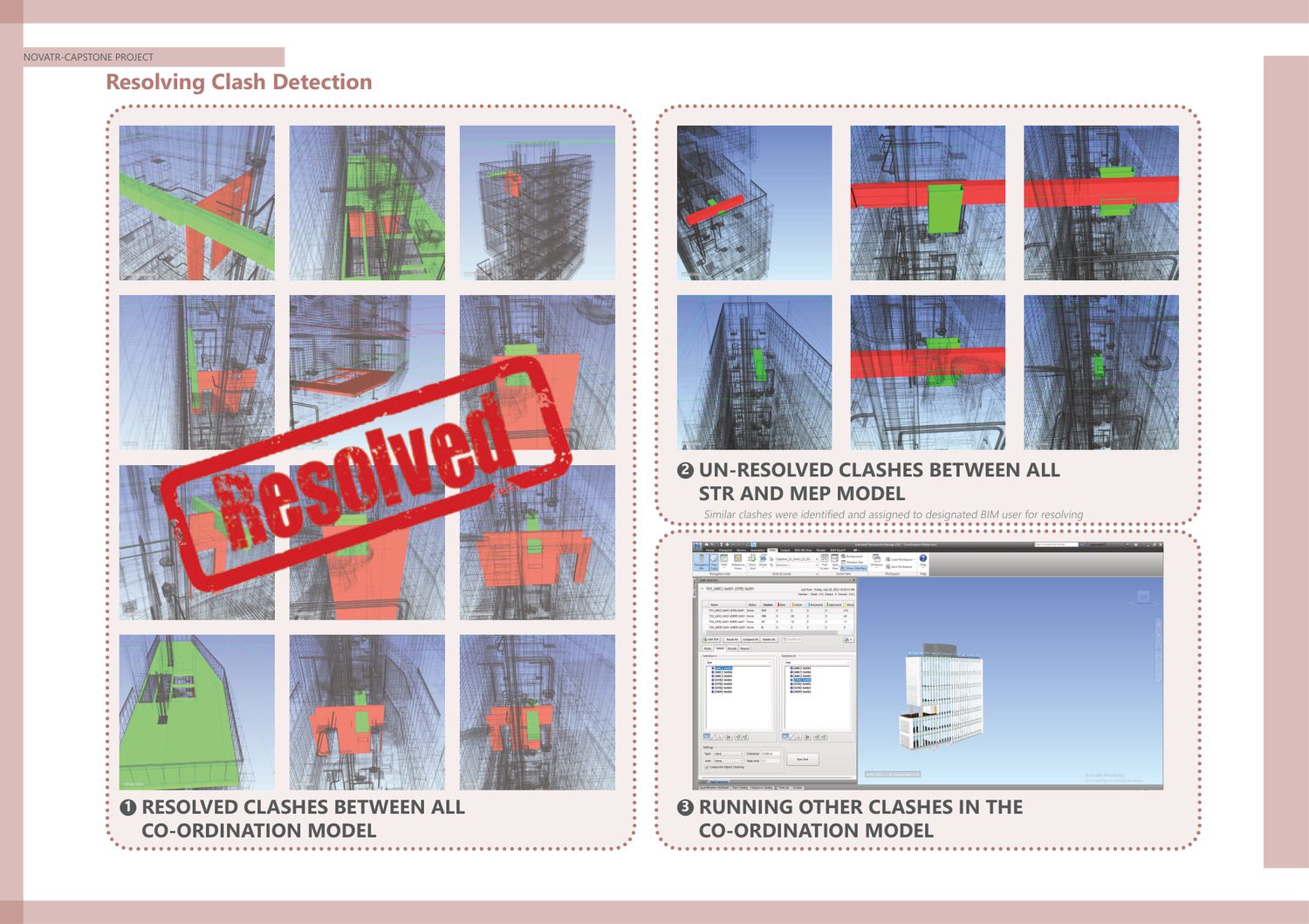
Then the part most portfolios skip: similar clashes grouped and assigned to the designated BIM user, resolved, and re-run to confirm. Resolved and unresolved states tracked separately.
4D and 5D
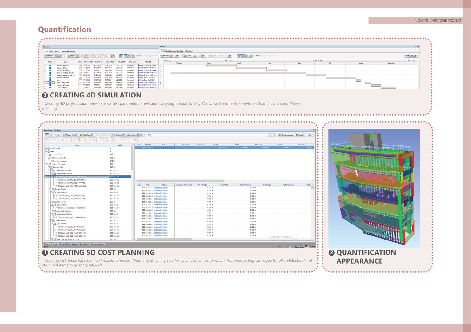
4D — a project parameter added in Revit as an instance text field, unique Activity IDs assigned per element, and task types built from a work breakdown structure with sets attached to each task name.
5D — quantification driven off the same WBS-linked task sets, producing cost planning from the model rather than alongside it.
That Activity-ID-per-element approach is the same instinct as the COBie work at Tolworth: put the identifier on the element and every downstream use gets easier.
Outcome
Graded A+ and certified BIM Professional. More usefully, it is the project on this site that demonstrates the full information-management chain — BEP, MIDP, clash matrix, 4D, 5D — rather than a single stage of it.